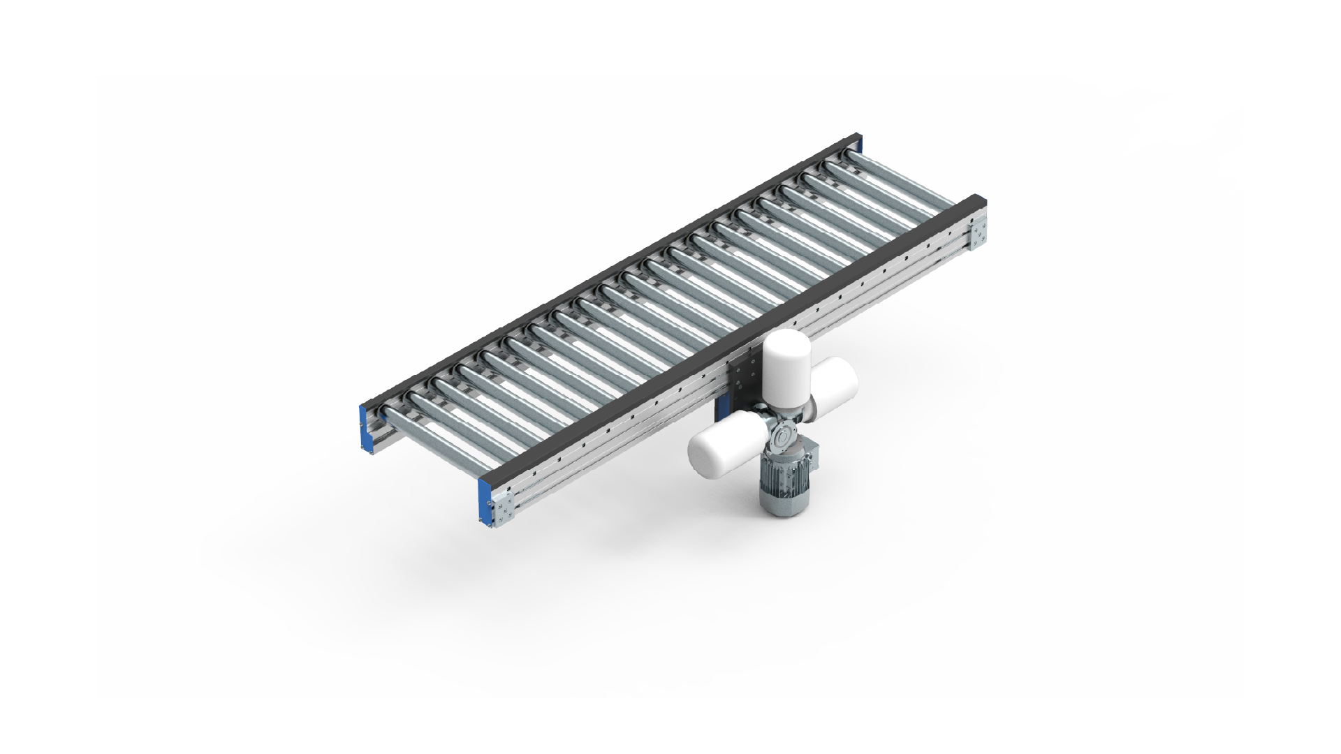
| A | Load width | min. 100 – max 1.500 mm |
| B | Drive position | C1 = external, C2 = internal |
| C | Track length | min. 460 mm − max. 12.000 mm |
| D | Motor reducer position | C1 = 1 – 2 – 3 – 4; C2 = 2 – 3 – 4 |
| E | Step between rollers | Ø50 min. 55 mm / Ø60 min. 65 mm |
| F | Roller diameter | Ø50/Ø60 |
| G | Speed | 3,8 − 39,5 m/min |
| H | Roller type | Fx = fixed,, Ac = accumulation, Pvc = PVC−coating, Zn = zinc-plated |
| Track load capacity | max. 20.000 N |
| Roller | Motor | Reducer | KW | m/min* |
|---|---|---|---|---|
| Ø50 | BN71B4 | BN 14 VF49 P i = 60; i = 45; i = 36 i = 28; i = 24; i = 18; i = 14; i = 10; i = 7 |
0,37 | 3,8 – 5,1 – 6,4 – 8,2 – 9,6 – 12,8 – 16,5 – 23 – 32,9 |
| Ø60 | 4,6 – 6,1 – 7,7 –9,9 – 11,5 – 15,4 – 19,7 – 27,6 – 39,5 |
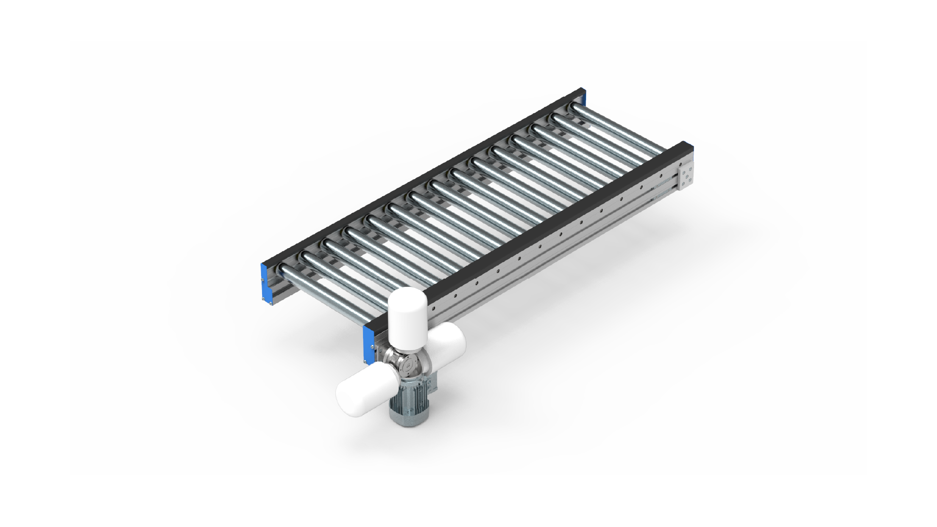
| A | Load width | min. 100 – max 1.500 mm |
| B | Drive position | L = left, D = right |
| C | Track length | min. 300 mm − max. 6.000 mm |
| D | Motor reducer position | 1 – 2 – 3 – 4 |
| E | Step between rollers | Ø50 min. 55 mm / Ø60 min. 65 mm |
| F | Roller diameter | Ø50/Ø60 |
| G | Speed | 3,2 − 33 m/min |
| H | Roller type | Fx = fixed, Ac = accumulation, Pvc = PVC−coating, Zn = zinc-plated |
| Track load capacity | max. 10.000 N |
| Roller | Motor | Reducer | KW | m/min* |
|---|---|---|---|---|
| Ø50 | BN63B4 | BN 14 VF30 P i = 60; i = 40; i = 30 i = 20; i = 15; i = 10; i = 7 |
0,18 | 3,2 – 4,8 – 6,4 – 9,6 – 12,8 – 19,3 – 27,5 |
| Ø60 | 3,8 – 5,8 – 7,7 – 11,6 – 15,4 – 23,1 – 33 |
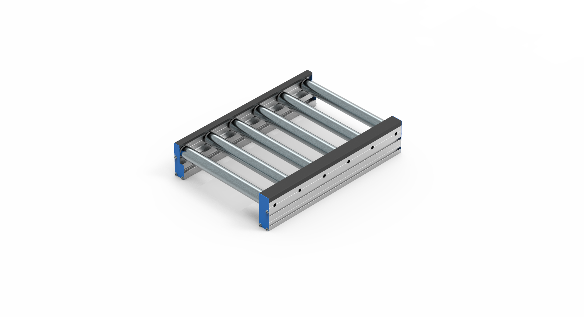
| A | Load width | min. 300 – max 1.200 mm |
| C | Track length | min. 60 mm − max. 1.000 mm |
| E | Step between rollers | min. 60 mm − max. 200 mm |
| G | Speed | 6 − 54 m/min |
| Track load capacity | max. 500 N |
| Roller | Motor | Transmission ratio | m/min* | ||
|---|---|---|---|---|---|
| Min. | Max. | ||||
| Ø50 | 24VDC | 12:1 | 1,8 | 75 | |
| 16:1 | 1,2 | 60 | |||
| 24:1 | 1,2 | 40 | |||
| 36:1 | 0,6 | 27 | |||
| 49:1 | 0.6 | 20 | |||
| 64:1 | 0.6 | 15 | |||
| 96:1 | 0,3 | 10 | |||
* m/min – The italic speeds are recommended.
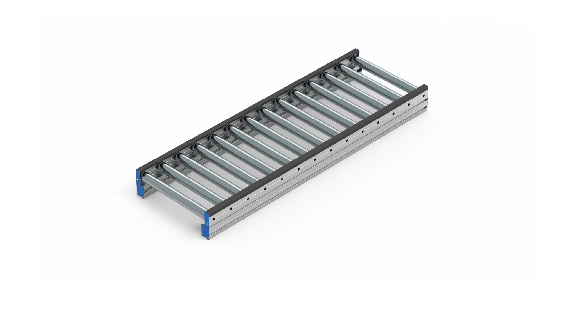
| A | Usable width | min. 100 – max 1.500 mm |
| C | Track length | min. 60 mm − max. 10.000 mm |
| E | Step between rollers | Ø50 min. 55 mm / Ø60 min. 65 mm |
| G | Roller diameter | Ø50/Ø60 |
| 1 | TYPE | 17NE | 17ND | 17NV |
| 2 | A | 100 – 1.200 | 100 – 1.200 | 100 – 480 |
| 3 | H | 250 – 1.200 | 500 – 1.200 | 250 – 1.200 |
| 4 | H1 | 250 – 900 | ||
| 5 | C | 45 – 155 |
| 1 | Ordering CODE | Name |
| 6 | 11121 | Angle piece – base |
| 11052 | Flanged nut | |
| 11047 | Hammer-head screw |
Order example
17RDMH – 400 – C1 – 2 000 – 3 – 120 – 50 – 3,8 – F
| A | Load width | min. 100 – max 1.500 mm |
| B | Drive position | C1 = external, C2 = internal |
| C | Track length | min. 460 mm − max. 12.000 mm |
| D | Motor reducer position | C1 = 1 – 2 – 3 – 4; C2 = 2 – 3 – 4 |
| E | Step between rollers | 4,6 – 6,1 – 7,7 –9,9 – 11,5 – 15,4 – 19,7 – 27,6 – 39,5 |
| F | Roller diameter | Ø50/Ø60 |
| G | Speed | 3,8 − 39,5 m/min |
| H | Roller type | Fx = fixed,, Ac = accumulation, Pvc = PVC−coating, Zn = zinc-plated |
| Track load capacity | max. 20.000 N |
Order example
17RDML – 400 – R – 2 000 – 3 – 120 – 50 – 3,2 – F
| A | Load width | min. 100 – max 1.500 mm |
| B | Drive position | L = left, D = right |
| C | Track length | min. 300 mm − max. 6.000 mm |
| D | Motor reducer position | 1 – 2 – 3 – 4 |
| E | Step between rollers | Ø50 min. 55 mm / Ø60 min. 65 mm |
| F | Roller diameter | Ø50/Ø60 |
| G | Speed | 3,2 − 33 m/min |
| H | Roller type | Fx = fixed, Ac = accumulation, Pvc = PVC−coating, Zn = zinc-plated |
| Track load capacity | max. 10.000 N |
Order example
17RDMM – 400 – 1 000 – 120 – 6
| A | Load width | min. 300 – max 1.200 mm |
| C | Track length | min. 60 mm − max. 1.000 mm |
| E | Step between rollers | min. 60 mm − max. 200 mm |
| G | Speed | 6 − 54 m/min |
| Track load capacity | max. 500 N |
Order example
17RTR – 400 – 1 000 – 120 – 50
| A | Usable width | min. 100 – max 1.500 mm |
| C | Track length | min. 60 mm − max. 10.000 mm |
| E | Step between rollers | Ø50 min. 55 mm / Ø60 min. 65 mm |
| G | Roller diameter | Ø50/Ø60 |
Order example
17NE – 100 – 250 – / – /
| 1 | TYPE | 17NE | 17ND | 17NV |
| 2 | A | 100 – 1.200 | 100 – 1.200 | 100 – 480 |
| 3 | H | 250 – 1.200 | 500 – 1.200 | 250 – 1.200 |
| 4 | H1 | 250 – 900 | ||
| 5 | C | 45 – 155 |
| 1 | Ordering CODE | Name |
| 6 | 11121 | Angle piece – base |
| 11052 | Flanged nut | |
| 11047 | Hammer-head screw |
"*" indicates required fields
Collection of our product catalogs
Provide us with some personal information so that we can give you access to the collection of our product catalogs in PDF format